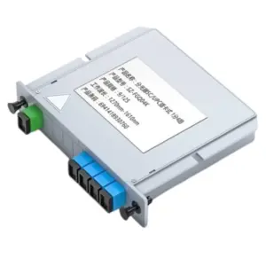
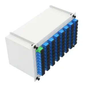
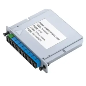
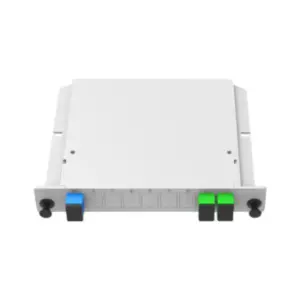
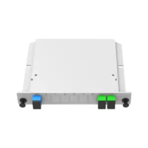
In this article, I will discuss in depth how splitter loss is calculated and what factors influence it. As an important indicator in fiber optic systems, splitter loss plays a key role in signal transmission and performance. Let’s uncover the mysteries of splitter loss and learn how to calculate and optimize it to provide you with efficient, reliable fiber optic solutions.
Fiber optic splitters are key components commonly used in fiber optic communication systems and are used to distribute optical signals to different destinations. However, fiber optic splitters will introduce certain losses during signal transmission, which may affect system performance and transmission quality. Therefore, understanding how to calculate optical splitter losses and the factors that affect loss is critical to designing and optimizing fiber optic communication systems.
The definition and significance of splitter loss
The definition and significance of splitter loss:
Optical splitter loss refers to the attenuation of optical power caused when a fiber splitter distributes optical signals to multiple output ports. When an optical signal passes through an optical splitter, part of the optical power will be lost or attenuated due to the transmission characteristics of light and the characteristics of the device itself. This loss is expressed in decibels (dB), with lower loss values indicating higher transmission efficiency.
Optical splitter loss is an important indicator in optical fiber communication systems and has the following significance:
-
System performance impact: Splitter loss directly affects signal transmission quality and system performance. Higher loss will cause signal attenuation and reduce signal strength, thereby affecting the optical power reaching the destination. This may result in transmission distance limitations, excessive signal attenuation, and increased bit error rates.
-
System design and optimization: Accurately understanding the loss characteristics of the optical splitter allows appropriate decisions to be made during the system design and optimization process. For example, in the case of signal transmission over a long distance, it is necessary to choose an optical splitter with lower loss to ensure effective transmission of the signal. In addition, splitter uniformity and loss consistency are also critical for applications that require even distribution of optical power, such as passive optical network (PON) systems.
-
System fault tolerance and reliability: Knowledge of splitter losses helps evaluate system fault tolerance and reliability. When there are multiple optical splitters in an optical fiber communication system, the accumulation of losses may cause the signal strength to be too low, thus affecting the normal operation of the system. By understanding and controlling optical splitter losses, system reliability can be improved and failure rates reduced.
Therefore, splitter loss is an important indicator that needs to be considered in optical fiber communication systems. Accurate assessment and control of splitter losses is critical for critical application scenarios that ensure signal transmission quality, system performance and reliability.
Calculation method of splitter loss
The calculation method of splitter loss includes the following basic formulas and steps:
-
Calculate input power (P_in): measure or know the power value of the input fiber. Usually measured in milliwatts (mW).
-
Calculate output power (P_out): measure or know the power value of each output port. For splitters with multiple output ports, the power of each output port needs to be calculated.
-
Calculate Split Ratio: Split Ratio refers to the proportion of input power allocated to each output port. For example, for a 1×4 optical splitter, the splitting ratio is 1:4, that is, the input power will be evenly distributed to the four output ports.
-
Calculate the splitter loss (Loss): The splitter loss can be calculated by the following formula:
Loss = 10 * log10(P_in / P_out)
Here, P_in is the input power and P_out is the output power. Loss is expressed in decibels (dB).
Here is a detailed explanation and calculation of each step:
-
Calculate input power (P_in): Input power refers to the power on the fiber entering the splitter. You can use a power meter or optical power meter to measure the power value on the input fiber. Record the measurement as P_in in mW.
-
Calculate the output power (P_out): For splitters with multiple output ports, the output power needs to be measured separately for each output port. Likewise, you can use a power meter or optical power meter to measure the power value on each output port. Record the power value of each output port as P_out1, P_out2, P_out3, etc.
-
Calculate the split ratio (Split Ratio): The split ratio represents the proportional relationship between input power distribution to each output port. For example, the splitting ratio of a 1×4 optical splitter is 1:4, that is, the input power will be evenly distributed to the four output ports. Determine the splitting ratio based on the type and specifications of the beam splitter.
-
Calculate the loss of the beam splitter (Loss): Use the above formula to calculate the loss of the beam splitter. Substitute the input power (P_in) and output power (P_out) into the formula to get the loss value (Loss) of the optical splitter. Loss is expressed in decibels (dB).
By performing the above steps, the loss value of the beam splitter can be calculated, which is crucial for evaluating the performance of the beam splitter and system design. Please note that this is a basic loss calculation method, and other factors may need to be considered in actual applications, such as mismatch loss, uniformity, etc.
Factors affecting splitter loss
There are many factors that affect splitter loss, the main factors include splitter type, wavelength, incident angle and connection quality. Each factor is explained below and relevant optimization strategies and suggestions are provided:
-
Optical splitter types: Different types of optical splitters (such as planar waveguide optical splitters, single-mode optical fiber splitters, etc.) have different loss characteristics. For example, planar waveguide splitters typically have lower losses, while single-mode fiber splitters have higher losses. Therefore, when selecting a beam splitter, the appropriate type should be selected based on specific application needs and performance requirements to minimize losses.
-
Wavelength: The loss of the optical splitter is closely related to the operating wavelength. Typically, optical splitters are designed to be optimized for a specific wavelength range. When the operating wavelength deviates from the design wavelength, losses may increase. Therefore, when selecting a beam splitter, you should ensure that it is suitable for the wavelength range used, and choose a beam splitter that matches the working wavelength as much as possible to reduce losses.
-
Incidence angle: The loss of the optical splitter is also affected by the incident angle of the optical signal. When optical signals enter the optical splitter at different angles, losses may increase due to the transmission characteristics of the light and the device structure. Therefore, when installing and using a spectrometer, attention should be paid to controlling the incident angle of the optical signal and trying to match it with the design requirements of the spectrometer to reduce losses.
-
Connection quality: The connection quality of the optical splitter also has an important impact on loss. Factors such as the quality of the fiber used in the connection, the accuracy and stability of the connector, etc. all affect loss. Ensuring the use of high-quality fiber optics and connectors, as well as proper fiber optic connections and securements, can reduce losses and improve system performance. In addition, regularly checking and maintaining the status of connections is key to keeping losses low.
In view of the above factors, the following are some optimization strategies and suggestions:
- Select a low-loss optical splitter type and make trade-offs based on specific application requirements.
- Determine the operating wavelength range of the optical splitter and select an optical splitter that matches the operating wavelength.
- Control the incident angle of the optical signal to match the design requirements of the optical splitter.
- Use high-quality optical fibers and connectors, and make proper fiber connections and fixations.
- Regularly check and maintain the status of the connection to ensure connection quality and stability.
By taking the above measures, the loss of the optical splitter can be minimized and the performance and reliability of the optical fiber communication system can be improved. In practical applications, further optimization and adjustment should be made based on specific system requirements and design parameters.
Analysis of practical cases of optical splitters
Assume we have an actual spectrometer system case. The following is an analysis of the relevant parameters and calculation process:
Parameters:
- Spectrometer type: 1×8 single-mode fiber splitter
- Operating wavelength: 1550 nanometers (nm)
- Input power: 10 milliwatts (mW)
-
Output power: The power on each output port is 1.5mW, 1.3mW, 1.4mW, 1.2mW, 1.1mW, 1.2mW, 1.3mW
-
Optical splitter loss calculation:
According to the loss calculation formula provided previously, we can calculate the loss of the optical splitter.
First, calculate the average of the output power:
P_out_avg = (1.5 + 1.3 + 1.4 + 1.2 + 1.1 + 1.2 + 1.3) / 7 = 1.28mW
Then, substitute the formula to calculate the loss:
Loss = 10log10(P_in / P_out_avg)
= 10log10(10 / 1.28)
≈ 8.07 dB
Therefore, according to the given parameters, the loss of this optical splitter is about 8.07 dB.
-
Parameters affecting and selecting a suitable beam splitter:
In this case, the impact of the following factors on splitter loss can be seen:
-
Optical splitter types: Different types of optical splitters have different loss characteristics. If low loss is a key factor, consider choosing other types of beamsplitters, such as planar waveguide beamsplitters.
-
Operating wavelength: The loss of the optical splitter is closely related to the operating wavelength. Make sure the optical splitter you choose matches the desired operating wavelength to reduce losses.
-
Output power: The size and uniformity of the output power will also affect the loss of the optical splitter. When selecting a beam splitter, you should consider the output power requirements and choose a beam splitter with lower loss and more uniform output power.
Considering the above factors, we can choose a suitable optical splitter according to the actual system requirements. If low loss is a key requirement, a lower-loss beamsplitter type can be selected, such as a planar waveguide beamsplitter. Additionally, ensure that the chosen beamsplitter is suitable for the desired operating wavelength range and has appropriate output power and uniformity.
It should be noted that the actual system design may also need to consider other factors, such as system budget losses, environmental conditions, etc. Therefore, when selecting an optical splitter, system needs, performance requirements, and actual application scenarios should be comprehensively considered to find the best optical splitter solution.
Testing and verification of splitter loss
Testing and verifying splitter loss is an important step to ensure the performance of the splitter system. The following are methods and steps for splitter loss testing and verification:
-
Test methods and equipment:
a. Optical power meter: Optical power meter is used to measure the power of optical signals. When testing the optical splitter loss, you need to connect an optical power meter to the output port of the optical splitter to measure the output power.
b. Light source: The light source is used to provide a stable optical signal as input. Common light sources include laser diodes (LDs) or lasers. Make sure the wavelength of the selected light source matches the operating wavelength of the beam splitter.
-
Verify that the loss is consistent with expected values:
a. Set up the test system: Connect the light source to the input port of the optical splitter, and connect the optical power meter to the output port of the optical splitter. Make sure the connection quality is good and select the appropriate fiber optics and connectors based on the system requirements.
b. Measure the output power: Use an optical power meter to measure the output power of the splitter. Record the power value of each output port.
c. Calculate loss: Based on the measured output power value, use the loss calculation formula to calculate the loss of the optical splitter. Compare with expected value.
d. Repeat the test: In order to ensure accuracy, the test can be repeated multiple times and the average loss value is calculated.
-
Ensure the stability of system performance:
a. Regularly check the connection: Regularly check the connection status of the optical splitter system, including the cleanliness of the fiber connection and connector. Make sure the connection is good and avoid loosening or contamination of the fiber end face.
b. Monitor temperature and environmental conditions: Spectrometer performance may be affected by temperature and environmental conditions. Ensure the system is under stable temperature and environmental conditions and monitor and record these parameters regularly.
c. Track performance changes: Conduct performance tests regularly and compare with previous test results. Perform troubleshooting and maintenance if losses exceed expected ranges or performance changes.
Through the above testing and verification steps, the consistency of the loss of the actual optical splitter system with the expected value can be verified and the stability of the system performance can be ensured. In actual applications, more detailed test plans and verification processes can be developed based on system needs and requirements.
Summary:
Thank you for reading our blog! We discuss in depth how splitter loss is calculated and the factors that influence it. As an important indicator in fiber optic systems, splitter loss plays a key role in signal transmission and performance.
When you choose our products, you will get high-performance optical splitters and professional technical support. We are committed to providing you with reliable, efficient fiber optic solutions that meet your needs and pave the way for your business success!
Splitter loss FAQ
Fiber splitter loss can be calculated by measuring the difference in optical power between the input and output ports of the splitter. The loss is typically expressed in decibels (dB) and can be calculated using the formula: Loss (dB) = 10 * log10 (Pout / Pin), where Pout is the output power and Pin is the input power.
Splitter loss in optical fiber refers to the amount of optical power that is lost when a signal is divided among multiple output ports of a splitter. It is a measure of the reduction in signal strength caused by the splitting process.
The formula for optical fiber loss depends on the specific scenario and components involved. Generally, the total fiber loss can be calculated by adding the individual losses of the fiber length, connectors, splices, and any other components in the optical path. The loss is typically expressed in decibels (dB).
A 50/50 optical splitter evenly divides the incoming optical signal into two equal output signals. The insertion loss of a 50/50 splitter is typically specified as 3.5 dB, which means there is a loss of approximately 3.5 dB in each output port compared to the input power.
The splitter loss in optical fiber depends on several factors, including the type of splitter, splitting ratio, and manufacturing quality. Generally, modern splitters have low insertion loss, ranging from a few tenths of a dB to a few dB, depending on the splitting ratio and other specifications.
A 2-way splitter evenly divides the incoming signal into two output ports. Each output port will experience a loss of approximately 3.5 dB compared to the input power. This splitting loss is due to the division of the optical power between the two output ports.
A 1:4 splitter, also known as a 4-way splitter, divides the incoming signal into four equal output ports. The splitter loss of a 1:4 splitter is typically specified as around 7 dB, meaning each output port experiences a loss of approximately 7 dB compared to the input power.

