Fiber splitters play an important role in optical networks. This article will focus on the working principle of fiber splitters. We will first briefly introduce the basic principles of fiber optic communication and explain the basic components of fiber optic communication systems. Next, we will define the function and structure of fiber splitters, explain its basic working process and implementation mechanism, and introduce the main types of splitters.
Then, we will focus on the key performance indicators of fiber splitters, including splitting ratio, insertion loss, isolation, and working bandwidth. We will analyze how these indicators affect the performance of splitters in practical applications. Finally, we will introduce the typical deployment scenarios of fiber splitters in optical networks such as FTTH and 5G, and analyze its advantages in various application scenarios.
Basics of fiber optic communication
The basics of fiber optic communication involve the use of optical fibers to transmit data and achieve high-speed and long-distance communication through the propagation of optical signals in optical fibers. The core components include lasers, optical fibers, photodetectors, and optical amplifiers. Fiber optic communication has the advantages of high bandwidth, low loss, and anti-interference.
Basic principles of optical fiber communication:
Optical fiber communication is a communication technology that uses light waves to transmit information in optical fibers. Its basic principles include:
(1) Light source emission:
- The optical transmitter (such as a laser or LED) converts electrical signals into optical signals.
- The optical signal contains the information to be transmitted, such as voice, data, etc.
(2) Optical signal transmission:
- The optical signal is transmitted through the optical fiber and propagates inside the optical fiber using the principle of total reflection.
- The optical fiber can be single-mode or multi-mode, with low loss and high bandwidth characteristics.
(3) Optical reception:
- The optical receiver (such as a photodetector) converts the received optical signal back into an electrical signal.
- The electrical signal is output after amplification, filtering and other processing.
This communication method that uses light waves to transmit information at high speed in optical fibers has higher bandwidth and lower loss than traditional cable communications.
Basic components of optical fiber communication systems:
The main components of optical fiber communication systems include:
(1) Optical transmitter:
- Light source equipment, such as lasers or LEDs.
- Convert electrical signals into optical signals.
- Includes light source driving circuits, etc.
(2) Optical fiber transmission section:
- Consists of single-mode or multi-mode optical fibers.
- Responsible for transmitting optical signals, using the principle of total reflection.
- May include relay equipment such as optical amplifiers.
(3) Optical receiving end:
- Light detection equipment, such as photodetectors.
- Convert the received optical signal back to an electrical signal.
- Including preamplifier circuits, filter circuits, etc.
(4) Other auxiliary equipment:
- Such as optical devices such as optical fiber connectors and optical fiber splitters.
- Used to connect, distribute or manage optical signals.
These basic components work together to form a complete optical fiber communication system and realize end-to-end optical communication. In short, optical fiber communication technology uses light waves to transmit information at high speed in optical fibers, with advantages such as large bandwidth and low loss. The core of the optical fiber communication system includes the optical transmitter, optical fiber transmission segment and optical receiver, supplemented by other optical devices. This communication method is widely used in various modern communication networks.
The working principle of fiber splitter
The fiber splitter evenly distributes the input optical signal to multiple output ports. It uses optical waveguide technology to split or synthesize signals, so that the optical signal is evenly distributed in each channel. It is often used in fiber optic networks to support multiplexing.
Function and structure of fiber splitter:
The fiber splitter is an optical network device whose function is to distribute the input single optical fiber signal to multiple output optical fiber ports. Its basic structure includes:
- Input fiber: introduce a single optical fiber signal into the splitter.
- Splitter chip: internal integrated optical waveguide structure to realize the splitting of optical signals.
- Output fiber: the split optical signal is transmitted from multiple output ports.
Basic working process of fiber splitter:
(1) Input optical signal enters splitter chip:
- Through input optical fiber, a single optical signal is introduced into the internal chip of the splitter.
(2) Optical signal is coupled and split inside the splitter:
- Inside the splitter chip, the input optical signal is split into multiple paths using the optical coupling principle.
- The power of the split optical signal will be distributed among the output ports according to the splitting ratio.
(3) The split optical signal is output to different optical fiber ports:
- The split optical signal is transmitted from multiple output ports of the splitter.
- Users can choose to access one or more output ports according to their needs.
Implementation mechanism of fiber splitter:
(1) Optical coupling splitting principle:
- The splitter uses optical waveguide technology inside and uses the optical coupling principle to achieve optical power distribution.
- The input optical signal is divided into multiple outputs through mutual coupling and interference between optical waveguides.
(2) Manufacturing process:
- The splitter can be manufactured using quartz-based PLC (Planar Lightwave Circuit) technology.
- Fiber fusion technology can also be used to achieve splitting by coupling between optical fibers.
Main types of fiber splitters:
- 1xN type: 1 input port, N output ports. Common splits include 1×2, 1×4, 1×8, etc.
- 2xN type: 2 input ports, N output ports. Used for symmetrical splitting in bidirectional networks.
- NxN type: N input ports, N output ports. Realize interconnection splitting between any ports.
Splitters with different splitting ratios can be flexibly selected according to application requirements to meet various splitting requirements in optical networks. In short, fiber splitters can distribute a single input optical signal to multiple output ports through optical coupling technology, and are an indispensable and important device in optical networks.
Performance indicators of fiber splitters
The performance indicators of fiber splitters include insertion loss (signal loss), return loss (reflection loss), uniformity (distribution uniformity) and wavelength range (applicable spectral range). These indicators determine the efficiency and signal quality of fiber splitters.
- Split ratio:
- The split ratio refers to the ratio of the input optical power distributed to each output port by the fiber splitter.
- Common split ratios include 1:2, 1:4, 1:8, 1:16, 1:32, etc.
- The more balanced the split ratio, the closer the optical power of each output port. This is conducive to flexibly meeting different application requirements.
- The split ratio is a key parameter that affects the power budget and transmission performance of the optical network.
- Insertion loss:
- Insertion loss refers to the total optical power loss from the splitter input to any output port.
- As the split ratio increases, the single-channel insertion loss will also increase accordingly.
- Lower insertion loss is conducive to maintaining the transmission quality and power margin of the optical network.
- Insertion loss is one of the important indicators to measure the performance of the splitter.
- Isolation:
- Isolation indicates the degree of mutual isolation between the output ports of the splitter.
- High isolation can prevent mutual coupling and interference between the output channels.
- Good isolation helps to ensure the independence and signal quality of each output channel.
- Isolation is a key performance indicator of the fiber splitter.
- Working bandwidth:
- The working bandwidth of the fiber splitter determines the frequency band range of the optical signal it can transmit.
- The broadband working characteristics are conducive to meeting the bandwidth requirements of high-speed optical networks.
- Different application scenarios have different requirements for bandwidth, and the appropriate splitter needs to be selected according to the requirements.
- Bandwidth is an important technical indicator that affects the applicability of fiber splitters.
In summary, the splitting ratio, insertion loss, isolation and working bandwidth of fiber splitters are the key parameters that determine their performance and applicability. Network planners need to select splitter products that meet technical and economic requirements based on actual application scenarios.
- Application of fiber splitters in optical networks
Fiber splitters are used in optical networks to distribute optical signals to multiple output ports and are widely used in FTTH, data centers and fiber sensor systems. They improve the flexibility and scalability of the network and support the access of multiple users and devices.
- Fiber-to-the-home (FTTH) network:
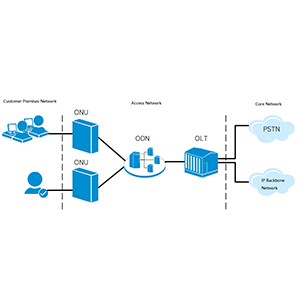
- Fiber splitters are widely used in the optical distribution segment of passive optical networks (PON).
- Distribute the single trunk fiber signal of the central office (OLT) to multiple user terminals (ONT).
- Use 1:N type splitter to flexibly meet the needs of user groups of different sizes.
- Low insertion loss is conducive to improving the transmission performance and power budget of PON network.
- 5G mobile communication network:
- Fiber splitters are used in the fiber backhaul section of 5G wireless access network.
- Distribute the fiber signal of the base station to the aggregation node of the core network.
- High reliability and broadband characteristics, suitable for high-speed transmission requirements of 5G network.
- Modular design is conducive to the flexibility and scalability of 5G network deployment.
- Broadcasting and TV Network:
- Fiber splitters are used for optical signal distribution in broadcasting and TV networks.
- Distribute optical signals on the trunk to user terminal devices in different regions.
- High isolation ensures the independence and signal quality between user channels.
- Meet the needs of broadcasting and TV networks for reliable transmission and unified management.
- Data Center Interconnection Network:
- Fiber splitters are used for optical fiber interconnection between devices within the data center.
- Achieve high-speed optical connections between servers, storage devices, etc.
- Modular design facilitates flexible configuration and rapid network expansion.
- Low power consumption helps improve the overall energy efficiency of the data center.
The main advantages of fiber splitters in the above application scenarios are as follows:
- High reliability: Based on PLC or fusion technology, it has excellent environmental adaptability and long-term stability.
- Low loss: Lower insertion loss is conducive to improving the transmission performance of optical networks.
- Flexible splitting: A variety of splitting port numbers meet the needs of networks of different scales.
- Integration: Miniaturization and modular design can simplify network equipment deployment.
Therefore, fiber splitters have become an indispensable key component in various high-speed optical networks, playing a key role in improving network performance and reliability.
Summary
Fiber splitters are key components for building high-performance optical networks. Our company has long focused on the research and development and application of fiber splitters and has rich practical experience. We provide various high-performance fiber splitter products, which are widely used in FTTH, 5G fronthaul, data center and other fields. Our fiber splitters adopt the industry-leading manufacturing process, and have achieved excellent levels in key performance indicators such as splitting ratio, insertion loss, isolation, etc.
At the same time, our engineering team will provide you with professional demand analysis and solution design services to ensure that the selected fiber splitter can meet your actual needs to the greatest extent. Contact us now to learn more. We will do our best to provide you with the best quality products and solutions.
Fiber Optic Splitter FAQ
A fiber optic splitter is a device used to divide an optical signal from one fiber into multiple output fibers, enabling the distribution of the signal to various destinations within a network.
A fiber optic splitter functions by using either optical waveguide technology or optical couplers to divide the incoming light signal into multiple signals. The splitter distributes the light with minimal loss and maintains signal quality.
The main types of fiber optic splitters are fused biconical taper (FBT) splitters and planar lightwave circuit (PLC) splitters. FBT splitters use fused and tapered optical fibers, while PLC splitters use planar lightwave circuits to achieve splitting.
An FBT splitter works by fusing two or more optical fibers together and then stretching and tapering them. This process creates a taper that splits the light signal into multiple outputs with varying degrees of power distribution.
A PLC splitter uses a planar lightwave circuit technology, where the optical signal is guided through a planar waveguide that splits the light into multiple channels with high precision and uniformity.
Key performance characteristics include insertion loss, which is the loss of signal power as it passes through the splitter; splitting ratio, which indicates the proportion of signal distribution; and uniformity, which refers to how evenly the signal is distributed among the outputs.
Insertion loss is the reduction in signal strength that occurs when the optical signal passes through the splitter. It is measured in decibels (dB) and represents how much signal power is lost due to the splitting process.
The numbers refer to the number of input and output ports. For example, a 1×2 splitter has one input port and two output ports, a 1×4 splitter has one input port and four output ports, and a 1×8 splitter has one input port and eight output ports.
Yes, fiber optic splitters can be designed for both single-mode and multi-mode fibers. Single-mode splitters are used for long-distance communication, while multi-mode splitters are used for shorter distances within local area networks.
Considerations include the required split ratio, the type of fiber (single-mode or multi-mode), operating wavelength, insertion loss, and environmental conditions such as temperature and humidity. Ensuring compatibility with your network’s specifications is crucial.


