Hello everyone! Optical fiber is the main transmission medium of modern communication network, and its link loss is a key factor affecting the transmission performance of optical fiber. Today gracyfiber is pleased to introduce to you in detail the definition, causes, measurement and optimization methods of optical fiber link loss, hoping to help you better understand and manage optical fiber networks. By mastering the key factors affecting optical fiber transmission, I believe you will be able to inject new impetus into network construction and maintenance, and bring greater impetus to your digital transformation.
What is optical fiber link loss
Let me introduce to you the definition and significance of fiber optic link loss in detail:
Definition and measurement of fiber optic link loss:
- Fiber optic link loss refers to the power attenuation suffered by optical signals during transmission.
- The loss of optical power is usually expressed in decibels (dB).
- Link loss can be measured by using test instruments such as optical power meters to calculate the difference between the input optical power and the output optical power.
- Link loss includes the accumulation of various factors such as the inherent loss of the optical fiber itself, connector loss, and splicing loss.
The impact of optical fiber link loss on transmission quality:
- Excessive link loss will cause serious attenuation of optical signal power, thus affecting the signal quality at the receiving end.
- When the optical power is lower than the sensitivity threshold of the receiver, the signal will not be received and demodulated normally.
- High loss will also reduce the signal-to-noise ratio (SNR), increase the bit error rate, and reduce reliability.
- Therefore, fiber link loss is one of the key parameters that affects optical transmission performance.
The importance of fiber link loss to network performance:
- Link loss directly determines the coverage of the optical fiber network and the spacing between relay stations.
- For long-distance transmission, excessive link loss will require more relay amplifiers and increase system costs.
- In high-speed optical networks, changes in link loss will also affect the selection of system modulation formats and detection schemes.
- Therefore, link loss must be fully considered in optical network planning and design to ensure the reliability and performance of the entire system.
In short, fiber link loss is a key technical parameter. It not only directly affects the quality of optical transmission, but also has an important impact on the performance and architecture of the entire optical network. In the design, deployment and maintenance of optical fiber communication systems, link losses need to be fully paid attention to and controlled.
What are the factors that affect fiber link loss
Let me introduce you to the main factors affecting fiber link loss in detail:
Intrinsic loss of fiber itself:
- Optical fiber materials and manufacturing processes determine the inherent loss characteristics of optical fibers.
- The inherent loss of single-mode glass fiber is usually around 0.2-0.3 dB/km, which is relatively low.
- The inherent loss of multimode glass fiber is slightly higher, generally 0.5-1.0 dB/km.
- The inherent loss of plastic optical fiber is relatively high, up to 3-10 dB/km.
Joint losses at connection points:
- Joint losses will occur at connections such as fiber optic connectors, couplers, and splice points.
- This is mainly due to factors such as the alignment accuracy and cleanliness of the fiber end face.
- Usually the loss of each connector is around 0.1-0.5 dB, and multiple connectors will accumulate losses.
Bending loss caused by fiber bending:
- The optical fiber will produce bending loss at the bend, which mainly depends on the bending radius.
- The smaller the bending radius, the greater the bending loss, generally between 0.1-1 dB.
- For single-mode optical fiber, bending loss is particularly serious and requires special attention.
The impact of environmental conditions on loss:
- Temperature changes will cause small changes in the refractive index of the fiber material, resulting in loss.
- Humidity changes will also affect the transmission characteristics of optical fibers, causing a certain degree of loss.
- Vibration and mechanical stress also increase fiber losses.
- These environmental factors are particularly important for some special applications.
In short, fiber link loss is caused by a combination of multiple factors. In practical applications, it is necessary to comprehensively consider various factors such as optical fiber materials, connection methods, and environmental conditions, and take effective measures to control and manage link losses to ensure the reliability and performance of optical communication systems.
How to analyze the main types of fiber link losses
Let’s take a closer look at the main types of fiber optic link losses:
Macroscopic bending loss and microscopic bending loss:
- Macro bending loss refers to the loss caused by optical fibers at large bending radii, which usually occurs during the optical fiber wiring process.
- Macroscopic bending loss is related to bending radius and bending angle, and is especially serious for single-mode optical fiber.
- Microscopic bending loss is the loss caused by tiny buckling and irregularities inside the optical fiber.
- Microscopic bending loss mainly occurs during the optical fiber manufacturing process and is related to material properties.
Insertion loss and reflection loss at fiber optic connectors:
- Insertion loss refers to the power attenuation of optical signals when passing through fiber optic connectors, mainly due to the end-face alignment accuracy and cleanliness.
- Reflection loss is the loss caused by the reflective interface at the optical fiber connector and is related to the connection quality.
- Insertion loss and reflection loss are the two main types of loss in fiber optic connectors.
Coupling loss during fiber coupling:
- Coupling loss occurs when the optical fiber is connected to other optical devices (such as light sources and detectors).
- Mainly due to incomplete power coupling caused by optical mode mismatch, end face position deviation, etc.
- Coupling loss is usually related to parameters such as the mode field diameter and numerical aperture of the optical fiber.
In general, the above loss types are the main factors affecting the transmission quality of optical fiber links. In practical applications, it is necessary to reduce these losses as much as possible by optimizing fiber cabling, improving connection quality, and matching optical devices to ensure that optical signals can be transmitted stably and reliably.
How to measure and evaluate fiber link loss
Let me walk you through common methods for measuring and evaluating fiber link loss:
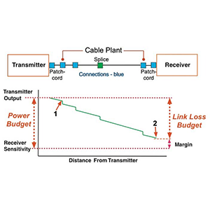
Loss measurement using optical power meter and light source:
- This method calculates the overall loss by measuring the difference between the light source output power and the link output power.
- When measuring, you need to use a calibrated optical power meter and a stable light source, and make sure the connection is good.
- Total loss = input power (dBm) – output power (dBm)
- This method is simple and direct, and can obtain the overall loss value of the entire link.
Adopt OTDR technology for precise diagnosis:
- OTDR (Optical Time Domain Reflectometer) is an optical time domain reflectometer that can accurately locate the loss point on the link.
- OTDR injects pulsed light signals into the optical fiber and measures the changes in backscattered optical power.
- By analyzing the OTDR test results, various loss sources can be accurately identified, such as joints, welding points, macro bends, etc.
- OTDR technology can help quickly locate and diagnose link problems, providing a basis for maintenance and management.
Assess link loss based on industry standards:
- For different application scenarios, there are usually corresponding industry standards and specifications.
- For example, the ITU-T G.652 standard stipulates that the total loss of single-mode fiber should be less than 0.4 dB/km.
- For data centers and enterprise networks, the TIA-568 standard provides more stringent link loss requirements.
- In practical applications, the acceptable link loss range needs to be determined based on relevant standards in the field.
In summary, to measure and evaluate fiber link loss, optical power meters, OTDR and other methods can be used, and link performance can be judged according to industry standards. These means can help us comprehensively understand the link status, discover and locate problems in time, and take targeted maintenance measures.
How to reduce and optimize fiber link loss
Let me explain in detail how to reduce and optimize fiber link loss:
Choose high-quality optical fibers and optical connectors:
- Choose optical fibers with excellent materials and good optical properties, such as low-loss single-mode glass optical fibers.
- Use high-precision, low-reflection fiber optic connectors to ensure end-face alignment and cleanliness.
- Reduce the number of fiber connection points as much as possible to reduce joint loss.
Careful planning and installation of fiber optic lines:
- Design the optical fiber wiring path reasonably and try to avoid sharp bends and too small bending radius.
- When installing optical fibers, be careful not to over-stretch or squeeze them to prevent macro-bending losses.
- Select the fiber length reasonably to avoid additional losses caused by excessive length.
Regular testing and maintenance of fiber optic links:
- Use tools such as OTDR to regularly detect link conditions to detect and locate problems in a timely manner.
- Clean and maintain key parts such as joints and welding points to reduce joint loss.
- Monitor changes in environmental factors, such as temperature, humidity, etc., and take necessary compensation measures.
- For long-term use of optical fibers, they must be replaced regularly to avoid performance degradation caused by aging.
Using advanced technology to improve transmission performance:
- Use technologies such as broadband optical amplifiers to compensate for link losses and extend transmission distances.
- Adopt technologies such as forward error correction (FEC) in high-speed transmission to improve anti-noise performance.
- Optimize the matching of light source and receiver to improve the overall optical coupling efficiency.
In general, reducing and optimizing fiber link losses requires comprehensive consideration from multiple levels such as fiber optic materials, network topology design, installation and maintenance, and advanced technology. Only through all-round optimization can the advantages of optical fiber communications be fully utilized and the reliability and performance of the entire network system ensured.
Summary
Optical fiber link loss is a key factor affecting optical fiber transmission performance and requires our great attention. The characteristics of the optical fiber material itself, joint loss at the connection, environmental factors, etc. may lead to an increase in link loss and directly affect the communication quality of the network. In order to reduce and optimize optical fiber link losses, we need to select high-quality optical fibers and connectors, carefully plan and install optical fiber lines, and conduct regular testing and maintenance.
By using professional measurement methods, such as optical power meters and OTDR technology, we can accurately locate and diagnose link losses and determine acceptable loss ranges based on industry standards. Our professional technical team is ready to provide you with a full range of optical fiber network support. If you have any questions during the process of managing and optimizing optical fiber links, please feel free to contact us for communication.
Fiber link loss FAQ
Fiber link loss refers to the signal attenuation or weakening that occurs as the optical signal travels through a fiber optic cable.
The primary causes of fiber link loss include fiber cable length, connector/splice losses, and signal absorption/scattering within the fiber material.
Fiber link loss is typically measured in decibels (dB) using an optical power meter or loss test set that compares the input and output optical power levels.
The acceptable level of fiber link loss depends on the application, but generally, link losses should be kept below 3-5 dB for most fiber optic communication systems.
You can estimate the expected fiber link loss by adding the losses from the fiber cable length, connectors, splices, and other components along the link.
Factors that influence fiber link loss include fiber type (single-mode vs. multi-mode), wavelength, connector type, cable length, and environmental conditions.
Yes, fiber link loss can be minimized by using higher-quality components, ensuring proper fiber termination and splicing, and keeping cable lengths as short as possible.
Troubleshooting steps may include inspecting connectors, cleaning fiber ends, testing individual components, and verifying the integrity of the fiber cable.
High fiber link loss can lead to poor signal quality, reduced transmission distance, and potential link failures in fiber optic communication systems.
Regular testing and documentation of fiber link loss, as well as preventive maintenance, can help ensure optimal performance and detect any degradation over time.