Link budget loss is an indispensable and important concept in the design of optical fiber communication systems. This article will focus on the definition of link budget loss and its role in the system. We will first define what is meant by link budget loss and explain its main influencing factors. Next, we will introduce the calculation method of link budget loss in detail, including loss items and their corresponding calculation formulas.
At the same time, we will also give a specific optical fiber communication link case to demonstrate the item-by-item calculation process of link budget loss. In addition, we will analyze various parameters that affect link budget loss, such as light source power, fiber loss, photoelectric converter sensitivity, etc. Finally, we will propose some technical measures to optimize link budget loss, such as increasing light source power and reducing connection loss.

What is link budget loss
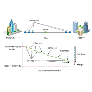
Let me introduce to you the concept of link budget loss and its role in optical fiber communication systems in detail: Link budget loss refers to the loss generated during the transmission of optical signals in optical fiber links, including fiber loss. , connector loss, welding loss, etc. Link budget loss is an important parameter in optical fiber link design, which determines the transmission distance and rate of the optical fiber link.
The definition and influencing factors of link budget loss:
1.Definition:
- Link Power Budget refers to the total power loss from the transmitter to the receiver in the optical fiber communication system.
- It is an important indicator to measure the transmission capacity of optical fiber links and directly affects the transmission distance and reliability of the system.
2. Influencing factors:
- The loss of the optical fiber itself mainly includes inherent loss and bending loss.
- Coupling losses in fiber optic splices and connectors.
- Insertion loss of intermediate equipment such as optical splitters and optical amplifiers.
- Transmission loss caused by scattering and absorption in optical fibers.
- Additional losses caused by factors such as ambient temperature and humidity.
The role of link budget loss in optical fiber communication systems:
1. Determine the transmission distance
- Calculate the maximum transmission distance of the system based on the light source power and receiving sensitivity.
- Ensure link losses are within the dynamic range of the source and receiver.
2. Guide system design
- Use link budget analysis to select appropriate light sources, optical fibers, connectors and other components.
- Determine the number and location of relay amplifiers required for the system and optimize the system structure.
3. Evaluate system performance
- Predict the transmission quality and reliability of the system by calculating the link budget loss.
- Determine whether the system can meet business needs and determine performance indicators.
4. Guide system maintenance
- Actually measure the link loss, compare it with the design value, find problems and deal with them in time.
- Predict equipment aging and failures by monitoring link loss changes.
In short, link budget loss is a key parameter in the design and maintenance of optical fiber communication systems, and can accurately reflect the transmission capability and reliability of the system. A reasonable link loss budget can guide the optimal design of the system and ensure high-performance transmission of optical fiber links.
Calculation method of link budget loss
Let me introduce to you the calculation method of link budget loss in detail: subtract the transmit power of the light source from the sum of all losses in the optical fiber link, and the result is the link budget loss. The calculation of the link budget loss needs to consider factors such as the type and length of the optical fiber, the type and number of connectors, and the number of splice points.
Main loss items affecting link budget loss:
1. Optical fiber loss
- The inherent loss of optical fiber is proportional to the length of the optical fiber. Common values are 0.2-0.5 dB/km.
- Fiber bending loss is related to the bending radius and the number of bends.
2. Connector loss
- The coupling loss of optical fiber connectors is about 0.3-0.5 dB for each pair of connectors.
- Additional loss caused by poor connection of fiber optic connectors.
3. Equipment insertion loss
- Insertion loss of intermediate equipment such as optical splitters and optical amplifiers.
- The insertion loss of each device is typically 3-10 dB.
4. Attenuation margin
- Consider additional losses caused by environmental factors, such as changes in temperature and humidity, etc.
- Usually leave 1-3 dB of attenuation margin.
Calculation formula and parameters of link budget loss:
Link budget loss (dB) = fiber loss + connector loss + equipment insertion loss + attenuation margin
Among them:
- Fiber loss (dB) = Fiber loss coefficient (dB/km) × Fiber length (km)
- Connector loss (dB) = number of connectors × loss per pair of connectors (dB)
- Equipment insertion loss (dB) = Σ Insertion loss of each device (dB)
- Attenuation margin (dB) = reserved additional loss (dB)
Calculation steps:
- Determine fiber loss coefficient and length.
- Statistics on the number of connectors and the loss of each pair of connectors.
- List all intermediate devices and their insertion loss.
- Allow appropriate attenuation margin.
- Add the above losses to get the total link budget loss.
Through this method, the link budget loss of the optical fiber communication system can be accurately calculated, providing a basis for system design and deployment.
Calculation example of link budget loss
Let me give you a specific optical fiber communication link case and demonstrate the item-by-item calculation process of link budget loss. The case assumptions are as follows:
The links of a certain optical fiber communication system are as follows:
- The fiber length is 20 kilometers
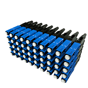
- Use SC/PC fiber optic connectors, 8 in total
- There is 1 optical splitter in the link, and the insertion loss is 6dB
- Reserve 2dB attenuation margin
Let’s calculate the total link budget loss for this link:
Fiber loss calculation:
Fiber loss coefficient = 0.3 dB/km
Fiber length = 20 km
Fiber loss = 0.3 dB/km × 20 km = 6 dB
Joint loss calculation:
Number of connectors = 8
Loss per connector pair = 0.3 dB
Joint loss = 8 × 0.3 dB = 2.4 dB
Equipment insertion loss calculation:
Optical splitter insertion loss = 6 dB
Device insertion loss = 6 dB
Attenuation margin:
Reserved attenuation margin = 2 dB
Total link budget loss calculation:
Total link budget loss = fiber loss + connector loss + equipment insertion loss + attenuation margin
= 6 dB + 2.4 dB + 6 dB + 2 dB
= 16.4 dB
Thus, the total link budget loss for this 20 km long fiber optic communication link is 16.4 dB. Through this specific calculation example, we can see that the calculation process of link budget loss includes several key items such as fiber loss, connector loss, equipment insertion loss and attenuation margin. Only through detailed analysis and calculation of these loss factors can the total loss of the entire link be obtained, which provides an important basis for system design.
Analysis of factors affecting link budget loss
Let me analyze for you the main factors affecting link budget loss:
The impact of light source power on link budget loss:
1. The higher the light source power, the greater the margin for link budget loss.
- High power light sources can compensate for more link losses.
- But too high light source power may cause nonlinear distortion.
2. The selection of light source power needs to match the receiving sensitivity.
- The light source power must be sufficient to overcome the link loss and meet the sensitivity requirements of the receiver.
- But if the power is too high, it will also increase the noise and interference at the receiving end.
The impact of fiber loss on link budget loss:
1. The higher the fiber loss coefficient, the greater the link budget loss.
- Intrinsic fiber loss and bending loss are the main factors.
- High-loss optical fiber will significantly shorten the link transmission distance.
2. The linear relationship between fiber length and loss.
- Every time the optical fiber length increases by 1 kilometer, the loss will increase by a certain value.
- It is necessary to reasonably control the length of optical fiber to avoid excessive loss caused by excessive length.
The impact of photoelectric converter sensitivity on link budget loss:
1. The higher the sensitivity of the receiving end, the greater the link budget loss margin.
- Highly sensitive receiver can detect weak light signals.
- Can withstand greater link losses and still function normally.
2. There is a trade-off between receiver sensitivity and cost, power consumption and other indicators.
- Improving sensitivity often requires increased circuit complexity and power consumption.
- Need to balance performance, cost, power consumption and other factors.
The impact of connector loss on link budget loss:
1. The coupling loss of the connector is an important component of the link loss.
- There is approximately 0.3-0.5 dB loss per pair of connectors.
- The greater the number of connectors, the greater the loss.
2. The quality of the connector and the status of the interface will also affect the loss.
- Interface contamination, poor contact, etc. will increase additional losses.
- Regular cleaning and maintenance is required to control connection loss.
In short, factors such as light source power, fiber loss, receiver sensitivity, and connector loss will significantly affect the link budget loss. These factors need to be considered comprehensively during system design, system parameters should be optimized, and link budget losses must be within an acceptable range.
Technical measures to optimize link budget loss
Let me summarize for you the main technical measures to optimize link budget loss:
Increase light source power:
- Use higher power light sources, such as power-enhanced semiconductor lasers
- Use equipment such as optical amplifiers to amplify the output power of the light source
- Optimize the coupling efficiency between light source and optical fiber to reduce energy loss
Reduce connection loss:
- Use high-performance optical fiber connectors, such as FC, SC, LC, etc.
- Strictly control the cleanliness and contact status of connectors
- Reduce the number of fiber optic connectors as much as possible and reduce connector loss
Choose the appropriate fiber type:
- Choose optical fiber with low loss characteristics, such as G.652.D standard single-mode fiber
- Prefer light sources and optical fibers with low peak wavelength (1550nm)
- Choose optical fiber with low bending loss to reduce the loss caused by bending
Selecting the appropriate fiber type is critical to optimizing link budget losses. Low-loss optical fiber can effectively reduce the loss of the optical fiber itself, while low-bending-loss optical fiber can avoid additional losses caused by improper fiber layout. By comprehensively considering the loss characteristics, bending characteristics and matching of the optical fiber with the light source, the total link loss can be minimized.
In addition, by optimizing the system structure layout and improving the sensitivity of the receiving end, the link budget loss can also be effectively compensated and reduced. In short, comprehensive optimization from multiple perspectives such as light source power, connection loss, and optical fiber characteristics is required to ensure that the link budget loss of the optical fiber communication system is controlled within an acceptable range.
Summary
Accurate calculation and optimization of link budget losses are crucial to building high-performance optical fiber communication systems. Our company has long been focused on the research and development and application of optical fiber communication technology and has rich industry experience. Our optical fiber communication products have reached industry-leading levels in key parameters such as light source power and fiber loss, which can significantly reduce link budget losses.
No matter what environment your optical fiber communication system is deployed in, we can provide you with customized solutions to ensure that the link budget loss is controlled within a reasonable range. At the same time, our professional team will provide you with comprehensive technical support, including link budget calculation guidance., Optimization scheme design, etc. Contact us now to learn more about our fiber optic communications products and link budget management services.
Link Budget Loss FAQ
Link budget is the calculation of the total amount of power or loss that can be tolerated in a communication link while still maintaining a minimum required signal level at the receiver.
Link budget loss refers to the sum of all the signal attenuations and losses that occur along the communication path, such as fiber optic cable loss, connector loss, splice loss, and other factors.
Calculating the link budget is crucial to ensure that the received signal has sufficient power to be detected and processed correctly by the receiver, especially in fiber optic and wireless communication systems.
The key components include fiber optic cable loss, connector loss, splice loss, system margin, and any other losses due to components or environmental factors.
Fiber optic cable loss is calculated by multiplying the fiber length by the attenuation coefficient of the fiber, which is usually provided by the fiber manufacturer.
Connector and splice losses can be obtained from the specifications provided by the component manufacturers or measured using specialized test equipment, such as an optical power meter.
System margin is an additional amount of loss that is included to account for unexpected degradations, aging, and other uncertainties in the communication link.
The total link budget loss is the sum of all the individual losses, including fiber cable loss, connector loss, splice loss, and system margin.
The required received power is the minimum signal level that the receiver needs to operate properly, which is usually specified by the receiver manufacturer or defined by the communication system requirements.
By comparing the calculated total link budget loss to the available link power budget (the difference between the transmitter output power and the required received power), you can determine if the link is feasible or if additional measures, such as using higher-power components or repeaters, are necessary.


