Fiber optic splitters undoubtedly play an important role in fiber optic communications. This article will focus on the splitting ratio characteristics of fiber optic splitters. We will first define the physical structure and working mechanism of fiber optic splitters, and explain how optical signals are split in splitters. Next, we will explain the meaning of the splitting ratio of fiber optic splitters and its calculation method, and explain the impact of different splitting ratios on the output power of optical signals.
We will analyze the impact of factors such as fiber type, wavelength, and splicing loss on the splitting ratio, and discuss how to optimize the splitting ratio of splitters by adjusting parameters. In addition, we will introduce common splitting ratios such as 1:2, 1:4, and 1:8, and compare the applicable scenarios of different splitting ratios in practical applications. Finally, we will explain the application of splitters in passive optical networks, FTTH, etc., and analyze the role of splitters with different splitting ratios in network design.
Basic Principles of Fiber Optic Splitters
Let me introduce the basic principles of fiber optic splitters in detail.
The physical structure and working mechanism of the optical fiber splitter:
(1) Physical structure:
- The optical fiber splitter is composed of two or more optical fibers fused together.
- The optical fibers are usually fused together by optical fusion or mechanical clamping.
(2) Working principle:
- When the optical signal enters the splitter from the input end, mutual coupling will occur between the optical fibers.
- According to the design, the optical signal will be distributed to different output ports to achieve optical signal splitting.
The splitting mechanism of the optical signal in the splitter:
(1) Optical power distribution:
- In the splitter, the input optical power will be distributed to each output port.
- The distribution ratio depends on the design parameters of the splitter, such as the fiber fusion length, refractive index, etc.
(2) Waveguide mode coupling:
- The light wave in the input fiber will couple with the waveguide mode of the fusion part.
- Different coupling strengths will result in the distribution of optical power to each output port.
(3) Wavelength selectivity:
- The optical fiber splitter can split the optical signal according to the wavelength selectivity.
- For example, a wavelength-selective splitter will split the optical signal to different ports according to the wavelength.
(3) Splitting ratio adjustment:
- By designing the physical structure parameters of the splitter, the splitting ratio of each output port can be adjusted.
- Meet the needs of optical signal distribution ratio in different application scenarios.
In short, the fiber splitter uses the coupling and mode interaction between optical fibers to distribute the input optical signal to multiple output ports. This splitting mechanism provides the physical basis for the functions of splitting and combining in optical communication systems. The fiber splitter is one of the key components in passive optical networks.
Overview of the splitting ratio of fiber splitters
Let me introduce the concept of the splitting ratio of fiber splitters and its impact on the output power of optical signals.
The meaning and calculation of the splitting ratio of fiber splitters:
(1) Definition:
- The splitting ratio of a fiber splitter refers to the distribution ratio of the input optical power between each output port.
- Usually expressed in percentage or dB.
(2) Calculation method:
- Assume a 2×2 fiber splitter, the input power is Pin.
- Then the power of output port 1 is P1, and the power of output port 2 is P2.
- Split ratio = P1/Pin × 100% or P2/Pin × 100%
(3) Ideal situation:
- Ideally, the split ratio of a 2×2 splitter is 50:50.
- That is, the input power is evenly distributed to the two output ports.
The impact of different split ratios on the output power of optical signals:
(1) Unbalanced split ratio:
- When the split ratio deviates from 50:50, the optical power of each output port will be unbalanced.
- The optical power of one output port will be greater than that of another output port.
(2) Increased power loss:
- Unbalanced split ratio will cause the total output power to be lower than the ideal 50:50 situation.
- That is, the total power loss will increase and the system performance will decrease.
(3) Impact of application scenarios:
- Unbalanced split ratio will affect the performance and stability of downstream devices.
- For example, the receiving device needs sufficient optical power, otherwise it will cause signal reception problems.
(4) Splitting ratio adjustment:
- The splitting ratio can be adjusted by designing the physical structure parameters of the splitter.
- To meet the needs of optical power distribution in different application scenarios.
In short, the splitting ratio of the fiber splitter is a very important parameter, which directly determines the optical power distribution of each output port. Reasonable design of the splitting ratio can ensure the stability and reliability of system performance and is one of the key considerations in passive optical network design.
Key factors affecting the splitting ratio
Let me analyze the key factors affecting the splitting ratio of the fiber splitter and how to optimize the splitting ratio by adjusting these parameters.
Key factors affecting the splitting ratio:
(1) Fiber type:
- Different types of optical fibers, such as single-mode fiber or multi-mode fiber, will affect the splitting ratio of the splitter.
- Because different optical fibers have different parameters such as mode field diameter and numerical aperture.
(2) Wavelength:
- The wavelength of the optical signal is also an important factor affecting the splitting ratio.
- The coupling strength of optical signals of different wavelengths in the splitter will be different.
(3) Fiber splicing loss:
- The loss at the fiber splicing will change the distribution of optical power and affect the splitting ratio.
- The greater the splicing loss, the more unbalanced the splitting ratio.
(4) Splitter structure parameters:
- The physical structure of the splitter, such as fusion length, refractive index, etc., will also affect the splitting ratio.
- The design of these parameters directly determines the propagation characteristics of the optical signal in the splitter.
Methods for optimizing the splitting ratio of the splitter:
(1) Select the appropriate fiber type:
- Choose single-mode fiber or multimode fiber according to the application scenario to obtain the ideal splitting ratio.
- Fiber parameter matching is very important for optimizing the splitting ratio.
(2) Control wavelength characteristics:
- The structural parameters of the splitter can be optimized for a specific working wavelength during design.
- To ensure that the ideal 50:50 splitting ratio is obtained at the target wavelength.
(3) Reduce splicing loss:
- Through precise fiber fusion splicing technology, minimize the loss at the splicing point.
- Reducing splicing loss helps maintain the stability of the splitting ratio of the splitter.
(4) Optimize the splitter structure:
- Adjust the splitter’s design parameters such as fusion length and refractive index distribution.
- To obtain the best optical power distribution ratio and achieve an ideal 50:50 split ratio.
In short, fiber type, operating wavelength, splicing loss and splitter structure parameters are key factors affecting the split ratio. By reasonably selecting and optimizing these parameters, the optical power distribution of the splitter can be made more balanced, thus meeting the needs of different application scenarios.
Common fiber splitter split ratio types
Let me introduce the common fiber splitter split ratio types and their applicable scenarios in practical applications.
Common fiber splitter split ratio types:
(1) 1:2 splitter:
- Splits 1 input port into 2 output ports.
- Ideally, the split ratio is 50:50, that is, each output port receives 50% of the input power.
(2) 1:4 splitter:
- Splits 1 input port into 4 output ports.
- Ideally, the split ratio is 25:25:25:25.
(3) 1:8 splitter:
- Splits 1 input port into 8 output ports.
- Ideally, the split ratio is 12.5:12.5:12.5:…
(4) Other split ratios:
- There can also be splitters with higher split ratios such as 1:16, 1:32, 1:64, etc.
- The higher the split ratio, the lower the power obtained by a single output port.
Applicable scenarios of different split ratios in actual applications:
(1) 1:2 splitter:
- Applied to scenarios requiring 2 outputs, such as FTTH optical splitters.
- Ensure that each output port has sufficient optical power.
(2) 1:4/1:8 splitter:
- Applied to scenarios that require multiple outputs, such as optical distributors in passive optical networks.
- Can support access to more end users.
(3) High split ratio splitter:
- Applied to scenarios that require lower output power, such as the terminal side of passive optical networks.
- Can support access to more users, but the access bandwidth of a single user may be limited.
In short, splitters with different split ratios can meet the requirements of optical power allocation and the number of user accesses in different scenarios. In practical applications, it is necessary to weigh and select the most appropriate splitter type based on the specific situation.
Application of Fiber Splitter in Network
Let me explain in detail the role of fiber splitter in passive optical network, FTTH and other application scenarios.
Application of Fiber Splitter in Passive Optical Network:
(1) Optical Splitter:
- 1:N splitter is used as optical splitter in Passive Optical Network (PON).
- Distribute optical signal from OLT to multiple ONU terminal devices.
- Typical split ratios are 1:4, 1:8, 1:16, etc.
(2) Function:
- Realize passive optical distribution in passive optical network.
- Support multi-user access and improve system utilization efficiency.
(3) Application scenarios:
- Used in PON networks such as GPON, EPON, and XG-PON.
- As a key passive device in ODN (optical network terminal).
Application of fiber splitters in FTTH networks:
(1) Optical Splitter:
- 1:2 splitter is used as an optical splitter in FTTH networks.
- Distribute the optical signal of OLT to two user-side terminal devices.
(2) Functions:
- Realize passive optical power distribution in FTTH networks.
- Provide sufficient optical power for each user.
(3) Application scenarios:
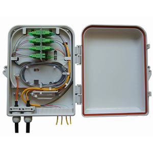
- Deployed in the optical splitter box on the FTTH user side.
- Provide optical signal access for single-family or dual-family users.
The role of splitters with different split ratios in network design:
(1) 1:2 splitter:
- Applicable to scenarios such as FTTH that require high optical power on the user side.
- Ensure that each user obtains sufficient optical power.
(2) 1:4/1:8 splitter:
- Applicable to scenarios such as PON that need to support more user access.
- Able to distribute optical signals to multiple users.
(3) High split ratio splitter:
- Applicable to cost-sensitive scenarios on the PON terminal side.
- Supports more user access, but the bandwidth of a single user may be limited.
In short, fiber splitters are indispensable key components in passive optical networks. Splitters with different splitting ratios play an important role in network design, meeting various optical power distribution requirements from the user side to the core network. Reasonable selection and deployment of splitters are the key to achieving high-performance optical networks.
Summary
Reasonable selection and correct deployment of fiber splitters are essential for building high-performance fiber networks. Our company has long focused on the research and development and production of optical communication equipment and its supporting products, and has rich industry experience. Our fiber splitter products have reached the industry-leading level in optical performance, reliability, etc., and can meet your demanding needs for network design.
Whether you need to deploy in a data center, a telecommunications office, or an FTTH access network environment, we can provide you with customized fiber splitter solutions. At the same time, our professional team will provide you with a full range of technical support, including on-site survey, solution design, and installation and commissioning guidance. Contact us now to learn more about fiber optic splitters.
Split Ratio FAQ
The split ratio, also known as the fiber optic splitter ratio, refers to the division of optical power in a fiber optic network, typically at a passive optical splitter.
Common split ratios include 1:2, 1:4, 1:8, 1:16, 1:32, and 1:64, although other ratios may also be used depending on the specific application.
As the optical signal is split, the power is divided among the output ports, with each output receiving a fraction of the input power based on the split ratio.
Factors include the desired number of output ports, the required signal levels at each output, the acceptable optical power budget, and the network topology.
Higher split ratios (more outputs) result in greater optical power losses, which must be accounted for in the overall power budget and link design.
Higher split ratios enable the servicing of more end-users from a single fiber, but also introduce higher optical losses and potentially reduced signal quality.
Splitters can be made using various optical waveguide technologies, such as fused biconical taper, planar lightwave circuit, or multimode interference (MMI) designs.
Split ratios are commonly used in passive optical networks (PONs), fiber-to-the-home (FTTH) deployments, and other fiber optic distribution applications.
Calculating the power budget involves considering the input power, the split ratio-based losses, and the other link-related losses to ensure sufficient optical power is available at the receiver.
Advancements include higher-density splitters, integrated splitter-coupler modules, and the use of wavelength-selective splitters for CWDM and DWDM applications.