Fiber splitters play an important role in optical communication networks. This article will focus on the optical loss of 1×8 fiber splitters. We will first define the structure and working principle of 1×8 fiber splitters and explain its advantages over other splitters. Next, we will deeply analyze the typical optical losses of 1×8 fiber splitters, including optical splitting loss, optical coupling loss, and optical transmission loss.
We will explain the formation mechanism of various types of losses and evaluate the performance of 1×8 splitters on these loss indicators. At the same time, we will calculate the total optical loss of 1×8 splitters and analyze the key factors affecting the total loss. Finally, we will introduce the process and design methods to reduce the loss of 1×8 splitters and explain the development trend of the loss level of 1×8 splitters in the future.
Basic characteristics of 1×8 fiber splitters
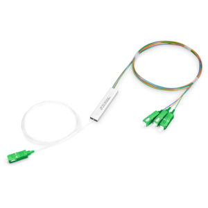
1×8 fiber splitters are optical devices that can divide a single fiber input into eight output ports for the distribution and distribution of optical signals. It has high reliability, low insertion loss, uniform optical power distribution and stable performance characteristics. It is widely used in optical distribution networks (ODN), optical sensor networks and optical fiber sensing applications in optical communication systems, supports multi-signal source connection and management, and provides important support for the expansion and improvement of optical networks.
Structure and working principle of 1×8 fiber splitter:
- 1×8 fiber splitter is a typical PLC (Planar Lightwave Circuit) splitter.
- Its basic structure includes:
- 1 fiber input end
- 1 Y-type splitter
- 8 fiber output ends
- Working principle:
- After the input single-mode optical signal enters the PLC chip, it is split into 8 optical signals by the Y-type splitter.
- Eight optical signals are output through different optical fiber output ends.
Advantages of 1×8 splitter compared with other splitters:
- High integration: 1×8 splitter adopts integrated optical path design, small size and light weight.
- High reliability: no mechanical movement, strong resistance to vibration and environmental influence.
- Low manufacturing cost: semiconductor manufacturing process is adopted, and the batch production cost is low.
- Stable performance: good stability of parameters such as optical path uniformity and isolation.
- Wide wavelength range: applicable to the entire optical communication window wavelength range.
- Good integration: can be integrated with other optoelectronic devices on the same substrate.
In general, 1×8 PLC splitter is widely used in fiber access network, passive optical network and other fields due to its high integration, high reliability and low cost. It is an important optical splitting device.
Typical optical loss of 1×8 fiber splitter
1×8 fiber splitter is a device used to distribute optical signals to eight output ports. Its typical optical loss is usually between 8-12 decibels (dB). This loss mainly comes from the energy dispersion of optical signals during the splitting process and the attenuation in the transmission path. Choosing a low-loss splitter can improve the overall performance of the system.
Optical splitting loss:
- Optical splitting loss is caused by the 1×8 splitter splitting the input optical signal into 8 outputs.
- Theoretically, the optical splitting loss of 1×8 splitter is 10dB, that is, the output power of each channel is 1/8 of the input power.
- In practice, due to the influence of manufacturing process and the uniformity of each split, the split loss may have a slight deviation.
Optical coupling loss:
- Optical coupling loss is caused by the coupling of optical signals from optical fiber into PLC chip and the coupling of optical fiber from chip.
- This coupling loss is related to the mode field matching degree of optical fiber and PLC chip, which can generally be controlled at 0.1-0.5dB.
Optical transmission loss:
- Optical transmission loss is caused by the transmission loss of optical waveguide inside PLC chip.
- The low-loss quartz material used inside PLC chip has a transmission loss of 0.1-0.2dB/cm. For 1×8 splitter, this loss is small.
Total optical loss:
- The total optical loss of a 1×8 PLC splitter is equal to the sum of the above three losses.
- The total loss is mainly affected by factors such as manufacturing process, material properties and device size.
Typical loss parameters:
- The typical total optical loss of a 1×8 PLC splitter is between 11-13dB.
- The loss parameters have a certain fluctuation range and need to be strictly controlled during the manufacturing process.
- Too high total loss will affect the system power budget, and a reasonable splitter needs to be selected.
In short, the optical loss of a 1×8 PLC splitter mainly includes splitting loss, coupling loss and transmission loss. The total loss can be controlled within a reasonable range by optimizing the process and structural design.
Technical measures to reduce the loss of 1×8 fiber splitters
To reduce the loss of 1×8 fiber splitters, the following technical measures can be taken: optimize the design of the splitter, select low-loss fiber materials, improve the accuracy and quality of fiber connections, adopt advanced fiber fusion technology, and strengthen the maintenance and testing of the splitter. These measures can effectively reduce the loss during signal transmission and improve the overall performance of the system.
Process and design methods to reduce loss:
(1) Optimize the optical splitting structure:
- Adopting an improved Y-type splitter design, such as a gradient splitting structure, can improve the splitting uniformity and reduce the splitting loss.
- Optimize the geometric size and material selection of the splitter to reduce the scattering and diffraction loss during the splitting process.
(2) Improve optical coupling performance:
- Use a step-by-step or tapered fiber-waveguide coupling structure to improve coupling efficiency and reduce coupling loss.
- Optimize the mode field matching between the waveguide and the optical fiber to reduce the coupling loss caused by mode field mismatch.
(3) Improve optical transmission performance:
- Use low-loss quartz material to manufacture PLC chips to reduce waveguide transmission loss.
- Optimize the geometric size and refractive index distribution of the waveguide to minimize bending and scattering losses.
(4) Improve manufacturing process accuracy:
- Apply advanced manufacturing processes such as photolithography and etching to improve the manufacturing accuracy of PLC devices.
- Optimize chip design and integration process to ensure the consistency and stability of each device parameter.
Future development trend of 1×8 splitter loss level:
- With the continuous optimization of manufacturing process and the advancement of material technology, the total optical loss of 1×8 PLC splitter will be further reduced.
- In the next 5-10 years, the typical total optical loss of 1×8 splitter is expected to be controlled below 10dB, or even reach 8-9dB.
- The emergence of ultra-low loss PLC splitter will further improve the transmission performance and reliability of optical fiber access network and passive optical network.
In short, by optimizing device structure design, improving manufacturing process, improving material performance and other measures, the optical loss level of 1×8 fiber splitter will continue to decrease to meet the needs of future high-speed optical network.
Summary
Low optical loss is the key performance indicator of 1×8 fiber splitters. Our company has been committed to the research and development and production of 1×8 splitters for a long time and has rich experience. We provide various high-performance 1×8 splitter products, which can be widely used in access networks, trunk transmission, data centers and other fields. Our 1×8 splitters adopt advanced manufacturing processes, have excellent optical performance and reliability, can effectively reduce optical signal attenuation, and meet your demanding transmission quality requirements.
At the same time, our team of engineers will provide you with professional selection guidance and integration services to ensure that the 1×8 splitter performs best in actual applications. Contact us now to learn more. We will do our best to provide you with the best products and solutions.
1×8 Fiber Optic Splitter FAQ
A 1×8 fiber optic splitter is an optical device that divides a single input fiber into eight output fibers, used for distributing optical signals in fiber optic networks.
It works by using optical technology to split the incoming signal into eight separate paths, ensuring that the optical signal is evenly distributed among the eight output fibers.
It is commonly used in fiber-to-the-home (FTTH) networks, telecommunications, data centers, and other optical distribution systems where a single signal needs to be distributed to multiple locations.
Specifications include insertion loss, splitting ratio uniformity, wavelength range, and physical dimensions. Typical insertion loss is around 10 to 15 dB, depending on the design and quality.
Insertion loss is the amount of signal power lost when the signal passes through the splitter. For a 1×8 splitter, low insertion loss is crucial to maintain signal strength and overall network performance.
Compared to other splitters like 1×4 or 1×16, the 1×8 splitter provides a moderate number of output paths, making it suitable for medium-scale distribution needs. It balances between the number of outputs and insertion loss.
A 1×8 fiber optic splitter can be equipped with various connectors, such as SC, LC, ST, or MTP/MPO connectors, depending on the specific requirements of the network.
Yes, but it requires an appropriate enclosure to protect it from environmental conditions like moisture, dust, and extreme temperatures to ensure reliable operation.
Considerations include avoiding excessive bending or stress on the fibers, ensuring proper alignment, and installing the splitter in a clean and stable environment to prevent damage and maintain performance.
Performance is tested using optical testing equipment to measure parameters such as insertion loss, uniformity of the splitting ratio, and return loss, ensuring that the splitter meets required specifications and performs reliably.